PDC and Arc Flash Investigation

PDC and Arc Flash Inves
PDC and Arc Flash Inves
PDC and Arc Flash Inves
Business Situation
Electrical systems commonly use fuses and circuit breakers to protect their electrical equipment. In the event that a failure occurs, it would be desirable that a short circuit would affect only the portion of the electrical system where the failure occurs, instead of the entire system. A protective device coordination study is used to analyze the tripping times for the series of overcurrent devices being compared, generally from the source through the largest branch circuit device. The curves are a logarithmically graphical representation of the performance characteristics of the devices at a base voltage of 480 volts.
The methodology is to optimize the selectivity of the devices. Selectivity is the isolation of a faulted circuit to the point of fault without disturbing any of the other protective devices in the system. A properly coordinated system has each of its protective devices adjusted to minimize the negative impact of equipment failures.
As a result of the PDC and Arc Flash Investigation, the Chemical Plant was able to determine the best settings for the new substation protective devices and identify the arc flash hazards, including appropriate label requirements per IEEE 1584 and PPE level required for each electrical bus.
Technical Situation
The main goal of the protective device coordination (PDC) study is to provide an optimal compromise between the desired system protection and system continuity goals. For maximum system continuity the protective devices have to be selected and adjusted so that only overcurrent protective devices nearest to the fault open and isolate the fault. While these goals are the ideal, most often the settings provided are a reasonable compromise between the often conflicting goals of service continuity and equipment protection/arc flash energy reduction. Where possible, by design, the protective device settings are provided such that the minimum amount of equipment is removed from service due to fault conditions.
For a given Chemical Plant, the protective device coordination (PDC) study was performed to determine the characteristics, ratings, and settings of protective devices to achieve optimum protection and selectivity in the new Power Substation of a Chemical Plant. The coordination curves were developed using the Paladin DesignBase PDC software. The coordination curves were plotted on log-log paper as operating time versus current magnitude to show protective device characteristics and coordination among protective devices.
The National Electric Code (NEC) guidelines are used for cable protection, transformer American National Standards Institute (ANSI) points, and transformer inrush current. Devices with different voltage levels are converted to a common base. If mis-coordination exists, the time-current curves are adjusted as far as possible without overlapping or crossing another curve. Often a compromise between protection and coordination must be made, and some overlap of characteristics may be necessary for the purposes of protection.
Solution
Paladin DesignBase software was used to perform the PDC and Arc Flash Investigation. Once the electrical system components were identified and laid out as a network, various study aspects were completed and described in detail below.
Time Overcurrent Protection
Protective relay operating times are provided by the manufacturer, and only the ideal expected relay operating time is plotted. Adequate coordinating time interval between protective relays and the upstream protective device should allow for relay operation time, circuit breaker operating time, and a safety margin to allow for relay calibration tolerances. IEEE recommends 0.2 seconds coordinating interval for microprocessor based relays.
Differential Protection
Differential protection is limited to a zone of protection where current flowing into the zone must equal current leaving the zone under normal conditions. This requires Current Transmitters (CT) to be installed at all points where current may enter or leave the zone of protection. Selection of CTs is critical to the proper operation of a differential scheme. The CTs must reflect the primary waveform with fairly high levels of accuracy during periods of high current or DC offset, which may be seen during through faults or transformer inrush.
Motor Protection
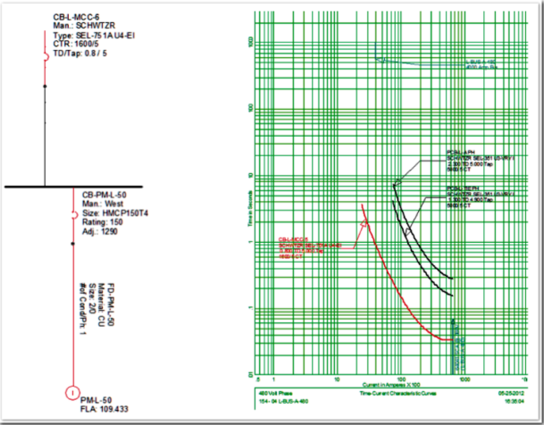
For large induction motors, above 1000 HP, the dynamic motor starting program has been employed in order to generate the real motor starting curves that were automatically transferred to the PDC program. However, time-current characteristic curves have been developed for each bus within the scope and objectives of the study. Each coordination plot is accompanied by a one-line diagram to aid in the understanding and analysis of the coordination plots.
The time-current coordination curves for each protective path were developed and are shown in several appendices. A description for each coordination path has been included to aid in understanding the degree of overcurrent protection provided, and the amount of coordination achieved between devices. Several protective paths were investigated in order to check the proper design, selectivity, and protective coordination. The figure below represents one path that was investigated, just as an example.
Arc Flash Investigation
Arc flash calculations are based on the IEEE 1584-2004 Standard and NFPA 70E-2012 regulations.Arc flash hazard analysis was performed in order to estimate:
• The level of Personal Protective Equipment (PPE) required at major pieces of equipment in the distribution system;
• Arc-flash boundary distance;
• Arc-flash incident energy at a typical working distance.
The DesignBase 5.0 release Arc Flash Program uses empirical equations based on test results given in IEEE-1584 to provide an estimate of the energy falling on a surface removed from a fault.
Procedure: Arc Flash – Worst Scenario Investigation
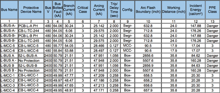
For the given Chemical Plant, the incident energy was estimated for the major buses in the system using the equations provided in the IEEE 1584 standard. Based on the energy values, the required PPE level is calculated using Table 130.7(C) (11) from NFPA 70E-2012.
Four scenarios were generated, as follows:
• Scenario 1: Minimum Short Circuit (both ties open, none of the SUB-L motors running)
• Scenario 2: 2.4 kV tie closed, 480 V tie open, all SUB-L motors running
• Scenario 3: Maximum Short Circuit (both ties closed, all SUB-L motors running)
• Scenario 4: 2.4 kV tie open, 480 V tie closed, all SUB-L motors running
Running DesignBase Arc Flash program for the four scenarios allows the program to automatically display the worst scenario for each system component as listed below:
Benefits
For this application, two distinct benefits were realized; the protective device coordination and the arc flash area. The PDC benefits include:
• Increased facility reliability – downtime alone can cost $7,000 - $200,000 per hour!
• Increased equipment protection, enabling engineers to easily perform protective device studies
• Increased operating efficiency, providing accurate operating characteristics
• Prevent damage by identifying underrated equipment
• Prevent damage by identifying overloaded equipment
The arc flash study benefits include:
• Minimize the effects of arcing incidents at your facility – or prevent these accidents from happening at all!
• Protect the lives and health of the personnel who work on or around your electrical equipment.
Increased operating efficiency, providing accurate operating characteristics
• Prevent damage to expensive electrical equipment by identifying abnormal conditions within the electrical
system (e.g., underrated equipment or equipment that is overloaded)
• Improve the reliability of your electrical system, which, in turn, raises the operating efficiency of your facility
• Help your company comply with the safety mandates of the OSHA General Duty clause, NFPA Standards, and
other applicable safety regulations
• Produce information that can reduce your company's workers'compensation costs and insurance rates.
• Provide important safety data for any subcontractors working at your facility
• Update all information related to your facility's electrical system – including its single-line diagram
• Guard your company against the high costs associated with arcing accidents: regulatory fines, legal fees, and
increased insurance premiums


