Short Circuit and PDE Analysis

Short Circuit and PDE A

Short Circuit and PDE A
Short Circuit and PDE A
Short Circuit and PDE A
Business Situation
It is essential for companies and factories to be aware of their power management system and have a trained electrician employed. There have been
 thousands of “death due to electric shock” cases that should keep business owners on a high alert about power system stability. Large factories, warehouses, and industrial units must have short circuit studies conducted on an electrical distribution system. The study not only helps troubleshoot electric problems but also gives the company a guideline on the design and implementation of its electrical systems.
The main objectives of the short circuit studies are:
• Verify that the rating of existing circuit interrupting equipment is higher than the calculated fault duty• Verify that the withstand rating of non-interrupting existing equipment is higher than the calculated fault
• Determine the basis for selective coordination of protective devices such as fuses, relay, and breakers
• Determine the withstand capability of switching devices during short circuit
The Short Circuit Study is based on IEEE-141 and IEEE-399 Standards, or IEC60909 and IEC61363. The maximum RMS symmetrical ½ cycle three-phase and line-to-ground bolted bus short-circuit currents are calculated.
All motor short-circuit contributions are included in the calculation. The calculation is based on ½ Cycle Network. The calculated short circuit current represents the highest current the equipment will be subjected to.
Technical Situation
A Case Study is provided where DesignBase tools have been used for assisting the design of a 2.4/0.480 kV substation interconnected to the existing Chemical Plant power system. However, the substation is part of a large Chemical Plant, and the system study was completed to determine the Bus Voltage Profile, Branch Loading, and Short Circuit Level in the plant system network and evaluate the switching and protective devices. Paladin DesignBase 4.0 software release was used to complete the project. This presentation focuses on Short Circuit and Protective Devices Evaluation.
The study has been completed for a Chemical Plant to determine the Bus Voltage profile, branch loading, and short circuit level in the network and evaluate the switching and protective devices for the 2.4 kV and 0.48 kV Substation.
Solution
Paladin DesignBase software was used to perform the Short Circuit and PDE analysis. Once the electrical system components were identified and laid out as a network, various study aspects were completed and described in detail below.
Paladin DesignBase 5.0 is state-of-the-art computer aided design and simulation software providing real solutions to any power system application. Based on the provided drawings and system data from the client, the Paladin DesignBase plant model has been generated. The electrical system extension of the Chemical Plant has been modeled as two separate models electrically interconnected to the existing plant system model.
Bus IDs, branch names, and equipment characteristics are shown on the DesignBase model drawing and project database. Equipment Naming has been input as per“One line diagrams provided by the client.” However, on completing this model the plant drawings and data from plant engineers were employed.
System Configuration and Scenarios
The following configuration was considered in short circuit calculation (as per plant engineer recommendations):
• Generators are ON
• Both utility lines are ON
• Available utility fault current is obtained from the model provided by the client
• All HV and MV CBs are closed
• All 2.4 kV breakers are closed
• All 480 breakers are closed, except the tie breakers that are normally open. The exceptions to the above are the breakers that are clearly marked in the model as future, out of service, or for spare circuits, etc.
• All motors are running
• Tie breakers of all double-ended substations are open
Having a close communication with the client, 4 scenarios were implemented:
• Both 2.4 kV and 0.48 kV tie CBs open
• The 2.4 kV tie CB closed and 0.48 kV tie CB open
• Both 2.4 kV and 0.48 kV tie CBs closed
• The 2.4 kV tie CB open and 0.48 kV tie CB closed
Assumptions:
In modeling the plant power system and performing the studies, the following assumptions were made:
• The impedance of protective devices is as per DesignBase Standard Library
• Motors data are as per data provided by the client or as per DesignBase library
• Feeder data are as per data provided by the client or as per DesignBase feeder library
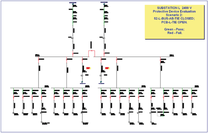
The short circuit results were provided and shown in 12 Appendices that are a part of the project. The summary of the results for the major buses in the system is shown below. Scenario 3 is the worst scenario: both 2.4 kV and 0.48 kV tie CBs are closed.
Tabulated Report 3 Phase and L-G bus fault current:
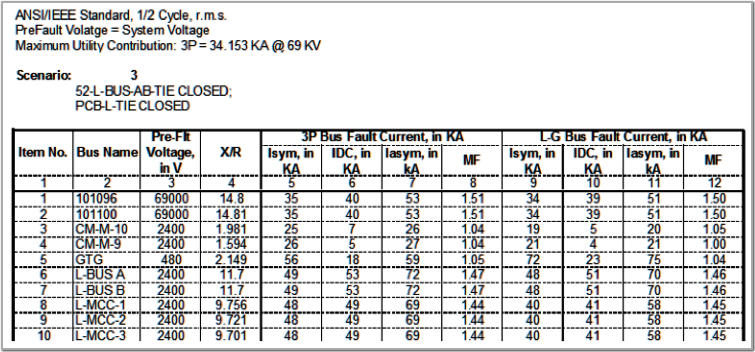
2.4 kV Substation:
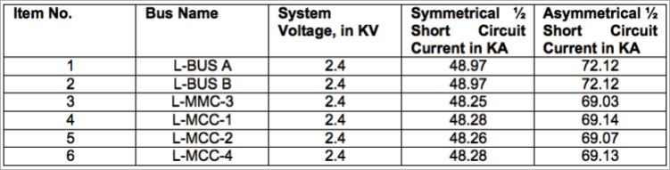
Conclusions – Short Circuit Analysis:
All the MV CBs in the 2.4 kV Substation were rated 41 KA. However, if the 2.4 kV Tie CB is closed, all the MV CBs cannot withstand during the short circuit.
Protective Device Evaluation:
Protective Device Evaluation was performed for all switching devices: HV, MV, and LV circuit breakers, switches, and fuses. One needs to highlight that where no information was available for interrupting time cycle for HV and MV breakers, and closing and latching current, the HV and MV breakers interrupting time was considered 5 cycles, and for asymmetrical closing and latching one has considered 1.6 x Max. interrupting current; for closing and latching peak was considered 1.414 x asymmetrical closing/latching current. These are as per IEEE standards and rules. Duty type for PDE was considered the total bus fault current. This is the most severe and conservative option. The PDE results were provided in several Appendices together with PDE visualization for easier identification.
Benefits
For this application, two distinct benefits were realized, the protective device coordination and the arc flash area. The PDC benefits include:
• Avoid catastrophic losses
• Increase the safety and reliability of the power system and related equipment
• Evaluate the application of protective devices and equipment
• Identify areas for improvement in the electrical system

