Power Flow Analysis

Power Flow Analysis
Power Flow Analysis

Power Flow Analysis
Business Situation
A load flow study determines how the electrical system will perform during normal and emergency operating conditions, providing the information needed to:
• Optimize circuit usage
• Develop practical voltage profiles
• Minimize kW and kVar losses
• Develop equipment specification guidelines
• Identify transformer tap settings
The Scope of Work involves the creation of a 3-phase steady state AC power system model of the 2.4 kV and 0.48 kV substations that are connected electrically to the initial plant model. In the current DesignBase model, the bus bars with the motors with a rated power less than 50 HP are considered in the motor schedule as per IEEE Brown Book. Large motors at 0.48 kV and medium voltage motors greater than 1.0 kV are modeled individually on their respective buses including all protective phase and ground over current relays and fuses. All substation low voltage power circuit breaker (LVPCB) are modeled. The entire plant system modeling is based on IEEE-399 “Brown Book.” All system equipment must have a corresponding one-line diagram symbol in the model. This means that there can be no hidden database models. The purpose is for the facility to easily see all equipment, its associated data, to be able to link documents to the equipment as a data repository, and to see problems right on the one-line.
By extending the Chemical Plant with the new substation the following were concluded:
• In the 2.4 kV Power Substation there were no overloads and no bus voltage violations (no voltage drops above 5%)
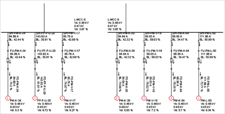
• In the 0.48 kV Substation there were no overloads, but there are voltage drops above 5%.
These were provided in the Power Flow Appendix. Also, it was concluded that as far as voltage drops are concerned the worst scenario is Scenario 1
Technical Situation
The Chemical Plant electrical distribution system is a complex network structure of electrical components, operating at voltages: 69 kV, 2.4 kV, 0.48 kV, and 208. The network is constructed with ring circuits but operates normally with radial feeds and normally open (NO) bus sections except the incoming 69 kV circuits.
Solution
Paladin DesignBase software was used to perform the Power Flow Analysis. Today in power system design a current procedure is “Simulation Based Design.” In the design process this approach allows the user to check the correctness of the proposed solutions based on several simulated scenarios.
A Case Study is provided where DesignBase tools were used for assisting the design of a 2.4/0.480kV substation interconnected to the existing plant power system. However, the substation is part of a large Chemical Plant, and the system study was completed to determine the Bus Voltage Profile, Branch Loading, and Short Circuit Level in the plant system network and evaluate the switching and protective devices. Paladin DesignBase 4.0 software was used to complete the project. This presentation focuses on Power Flow Analysis.
Paladin DesignBase 5.0 is state-of-the-art computer aided design and simulation software providing real solutions to any electrical application. Based on the provided drawings and system data from the client, the Paladin DesignBase model has been generated. The electrical system extension of the Chemical Plant has been modeled as two separate models electrically interconnected to the existing plant system model.
Bus IDs, branch names, and equipment characteristics are shown on the DesignBase model drawing and project database. Equipment Naming has been input as per “One line diagrams provided by the client.” However, in completing this model the plant drawings and data from plant engineers were employed.
To insure compliance with IEEE Standards, no exceptions or substitutions to the performance specification are allowed. The plant system model generated is made up of multiple model drawings that are electrically interconnected. All one-line symbols are spaced properly to facilitate viewing results on the one-line diagram while using back annotation.
The following steps were implemented:
• Close communication with design engineers and contractors
• Getting the proposed design data:
− System layout: one line connection diagram
− Bus voltage magnitude and voltage phase at the substation PCC
− Short circuit contribution at the substation PCC
− Feeder data and length
− XFMR type, manufacturer and XFMR data
− Electrical motors data, location, motor switching equipment
− Electrical loads, location, and estimated % running
• Based on the above input information, the substation model in DesignBase environment has been generated
• Having a close communication with the client, 4 scenarios were implemented:
− Both 2.4 kV and 0.48 kV tie CBs open
− The 2.4 kV tie CB closed and 0.48 kV tie CB open
− Both 2.4 kV and 0.48 kV tie CBs closed
− The 2.4 kV tie CB open and 0.48 kV tie CB closed
Once the substation model was completed, Power Flow was run. One needs to understand that the Power Flow convergence is the simplest way of checking if the given power system is feasible and the input data are consistent. During the power flow, we should not have large bus voltage drops (above 10%) and no more than 120% branch overloading. The main objectives of the Power Flow studies are:
• Verify that the input data for the system are consistent, and the system is feasible
• Verify that the bus voltages are within the limits +/- 5%
• Verify that the branches loading are within the limits, less than 80% loadings
• Verify that the power transformers loading are within the limits, less than 80% loadings
• Determine if the feeder sizes are correct
Power Flow System Configuration and Scenarios
Power Flow study is performed at 40°C ambient temperature to provide conservative bus voltage drop. The following configuration was considered in Power Flow (as per plant engineer recommendations):
• Generators are ON
• Utility lines are ON
• Available utility fault current is obtained from the model provided by the client
• All HV and MV CB are closed
• All LV CBs are closed, except the tie breakers that are normally open
• The exceptions to the above are the CBs that are clearly marked in the model as future, out
of service, or for spare circuits, etc.
• All motors are running
• Tie breakers of all double-ended substations are open
• Power Flow is run at 40°C ambient temperature
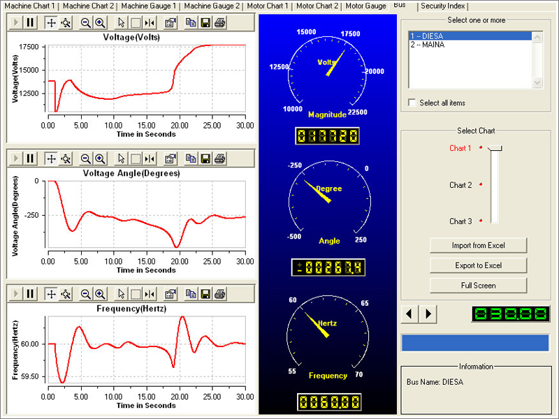
Bus Voltage Violation - Visualization
Benefits
Load flow studies are performed using computer software that simulates actual steady-state power system operating conditions, enabling the evaluation of bus voltage profiles, real and reactive power flow, and losses. Conducting a load flow study using multiple scenarios helps ensure that the power system is adequately designed to satisfy your performance criteria. A properly designed system helps contain initial capital investment and future operating costs. For this application, the power flow analysis benefits include:
• Decrease unexpected downtime
• Reduce operating and maintenance costs
• Get more capacity out of existing assets